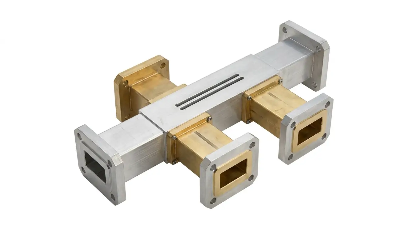
What Is a Waveguide Directional Coupler and Where Is It Used? Leave a comment
Imagine tapping a water pipe so a tiny trickle flows into a gauge, while the main flow carries on untouched. A waveguide directional coupler does the same job for microwave power. It siphons off a small, known fraction of the signal so you can measure it, without disturbing the main transmission path.
What Is a Waveguide Directional Coupler?
It’s a passive four-port waveguide component. Two ports form the main line; the other two give you a sample of the signal.
| Port | Role |
| Input | Where power enters |
| Output (through) | Carries most of the power onward |
| Coupled port | Delivers a small, fixed fraction of the forward power |
| Isolated port | Normally terminated with a matched load |
The key word is directional: the coupled port only “sees” power traveling in one direction. That lets you tell forward power from reflected power.
How It Works
Two waveguide sections share a common wall, with small openings (apertures) cut through it. Energy leaks through these openings and combines in phase at the coupled port. Going the other way, it cancels out. Spacing and size of the apertures decide how much signal is coupled and how well the directions are separated.
Specs That Matter
- Coupling factor (dB): how much power reaches the coupled port. Common values: 10, 20, 30, 40 dB
- Directivity (dB): how well it separates forward from reflected signal. Higher is better
- Insertion loss: power lost on the main line. Lower is better
- VSWR: how well matched the ports are
- Frequency band: must match the waveguide size (e.g., WR-90 for X-band)
- Power handling: peak and average ratings
Where Is It Used?
| Application | What the Coupler Does |
| Radar systems | Samples transmit power for monitoring and calibration |
| Satellite communication | Monitors uplink power at the feed |
| Microwave test and measurement | Feeds a power meter or spectrum analyzer safely |
| Reflected-power protection | Detects high VSWR so the system can shut down before damage |
| Telecom and microwave links | Tracks transmitter output and health |
| Industrial and medical microwave systems | Keeps heating or therapy power under control |
| Lab and research setups | Splits off a signal for analysis |
Directional Coupler vs Other Components
- vs Power divider: a divider splits power roughly evenly; a coupler takes only a small sample
- vs Isolator: an isolator blocks reflected power; a coupler measures it
- vs Tee junction: a tee splits power with no direction sensitivity or controlled ratio
How to Choose One
- Match the waveguide size and flange type to your system
- Pick the coupling value your meter can handle (20 to 30 dB suits most monitoring)
- Check directivity, since it affects reflection-measurement accuracy
- Confirm power rating for your transmitter, with headroom
- Terminate the isolated port properly with a matched load
Common Mistakes
- Leaving the isolated port unterminated
- Ignoring coupling flatness across the band
- Choosing coupling too low, which sends excess power to sensitive instruments
- Mismatched flanges causing leakage and added reflections
- Forgetting that coupled-port readings must be corrected by the coupling factor
A 20 dB coupler sends about 1% of the input power to the coupled port.
Yes. Connect it in reverse, or use a dual-directional coupler for forward and reflected readings at once.
For high power and high frequencies, yes. Waveguide has lower loss and handles more power.
Only slightly. Insertion loss is typically a fraction of a dB.