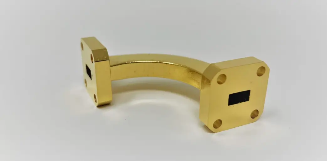
E-Plane vs H-Plane Waveguide Bends: What’s the Difference? Leave a comment
E-Plane vs H-Plane Waveguide bends redirect microwave signals without breaking the transmission path. Both bend types change the direction of the guide, but they do it in different planes relative to the electromagnetic field. Choosing the wrong one can force awkward routing, extra components, or higher signal reflection.
Quick Refresher: The Fields Inside a Waveguide
In a standard rectangular waveguide (dominant TE10 mode):
- E-field (electric): runs parallel to the narrow wall
- H-field (magnetic): loops in the plane parallel to the broad wall
The bend names come from which of these planes the guide is bent in.
What Is an E-Plane Bend?
An E-plane bend curves the waveguide in the plane of the electric field.
- Broad walls are bent or curved
- Narrow walls stay straight and parallel
- Often called an E-bend
What Is an H-Plane Bend?
An H-plane bend curves the waveguide in the plane of the magnetic field.
- Narrow walls are bent or curved
- Broad walls stay flat
- Often called an H-bend
Key Differences at a Glance
| Feature | E-Plane Bend | H-Plane Bend |
| Bend plane | Plane of the E-field | Plane of the H-field |
| Curved walls | Broad walls | Narrow walls |
| Straight walls | Narrow walls | Broad walls |
| Field orientation after bend | E-field stays perpendicular to the bend axis | E-field stays parallel to the bend axis |
| Typical use | Turning the guide across its narrow dimension | Turning the guide across its broad dimension |
Curved vs Mitered Bends
Both types come in two constructions:
- Curved (radius) bends: smooth arc, lowest VSWR, best for high-frequency or high-power systems
- Mitered bends: sharp corner with chamfered cut, more compact, slightly narrower bandwidth
A larger bend radius generally means lower reflection and better performance.
Performance Factors to Check
- VSWR: lower is better (values such as 1.05–1.10 are common in quality bends)
- Frequency range: must match the waveguide size (e.g., WR90: 8.2–12.4 GHz, WR75: 9.84–15 GHz)
- Material and plating: copper or aluminium body, silver-plated interior for low loss
- Flange type: must match your existing system (e.g., FBP100, FBP120)
- Bend angle: 90° and 45° are the most common
How to Choose the Right Bend
Choose an E-plane bend if:
- Your layout requires turning across the narrow dimension of the guide
- The routing space is limited along the broad wall direction
Choose an H-plane bend if:
- Your layout requires turning across the broad dimension
- Clearance is available on the narrow-wall side
In most installations, the choice is dictated by port orientation and available space. Electrically, both perform well when properly designed for the operating band.
Common Applications
- Radar systems
- Satellite and terrestrial communication
- Microwave test benches
- Industrial RF and heating systems
Final Thoughts
E-plane and H-plane bends differ in which walls curve and which plane the field bends in. Match the bend to your waveguide size, frequency band, flange type, and routing layout, and prioritize low VSWR and quality plating for reliable performance.
Looking for precision waveguide components? Explore E-Plane and H-Plane Waveguide Bends at YCH Solutions.